The goal of using the line gun is to create a taught line across the creek by which to pull the Sontek Hydroboard back and forth to make a discharge measurement. The projectile is fired across the creek from the “shooting side” and retrieved on the “receiving side.” The main line is then attached to the gun’s temporary line and pulled across the creek by staff on the receiving side. In most instances, the main line is then attached to existing eye bolts using carabiners and other ropes; in other instances, trees, vehicles and other sturdy objects may be used. Below are the steps for pressurizing and firing the line gun.
Use an allen wrench with key cut to make sure the valve on projectile is open (this will allow residual pressure to bleed out of projectile tank and allow pressure from SCBA tank to enter when desired)
Attach yoke to SCBA tank and projectile
Close bleed valves on the SCBA tank side and gun side of the yoke
Open SCBA tank valve and allow pressure to build to 1800 PSI, then close SCBA tank valve
Close projectile tank valve using the allen wrench with key cut, then bleed residual pressure from the lines using bleed valves at each end of the yoke
Removed yoke from SCBA tank and projectile
Pull black line tight, align the projectile and slide the projectile into gun
Attach black line to release pin using carabiner
Unfold stock on line gun
To charge line gun, close valve and check pressure
Release safety (if safety doesn’t release, close valve and bleed off extra pressure)
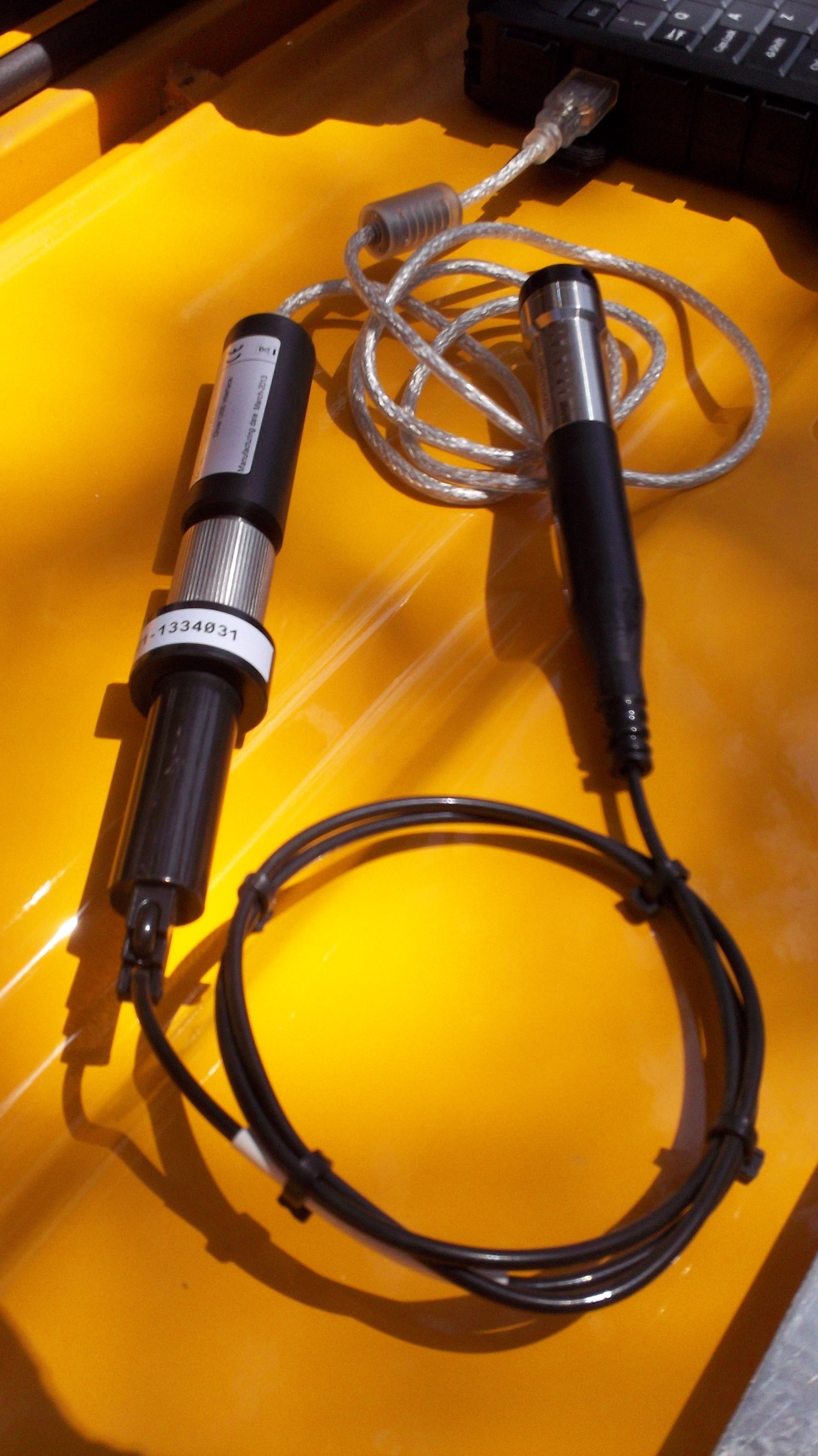
At several locations, Mini-Divers have been installed as a redundant water level sensors to the existing gas purge systems. With a 5-minute data logging setting, the internal memory of the Divers will be full in ~83 days. There is no memory wrap feature and the Divers must be stopped/started in order to erase existing data. Data for the Mini-Diver and BaroDiver must be downloaded individually.
Connect the threaded end of the USB interface cable to the Baro-Diver
The basic parts of a wire weight gage include a drum wrapped with a single layer of cable, and a weight attached to the end of the cable. A readable disc, graduated in tenths and hundredths of a foot is attached to the side of the drum. A Veeder counter, reading in whole feet is also included. One complete turn of the drum represents one foot of vertical movement of the weight. To take a reading of stage, perform the following:
Open the wire weight gauge house
Move the checkbar forward so it rests in position under the weight, if not already in position
While grasping the drum crank handle, disengage the pawl and lower the weight until it touches, but not fully rests on the check bar
Read the interval at the pointer on the graduated disc (the numbered hash marks correspond to tenths and five-hundredths of a foot graduations and the small hash marks correspond to one-hundredth foot increments)
If the check-bar value does not match, perform the following inspections:
Make sure the check-bar is set correctly
Check that the cable is wrapped on the drum properly and the threading sheave is positioned properly, directly above the wrap on the drum
Make sure the graduated disc is not slipping (caused by loose clutch screws)
Check the Veeder counter for proper operation (occasionally the counter is not synchronized with the graduated disc and will not turn over to the next whole foot in synchronization with the disc
If the check-bar value is satisfactory, slide the bar back and slowly lower the weight to the water surface (the weight should only touch the water surface enough to form a distinctive “V” shape on the water surface)
Read the Veeder counter and disc as previously described
Record the stage height on the front sheet
Wind in the weight.
Confirm the check bar elevation and reengage the pawl before closing and locking the wire weight gauge enclosure
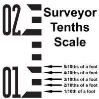
Staff gauges a read to the nearest 1/100th of a foot, which requires some estimation of the last significant digit, since gradations are only marked for each 1/10th of a foot.
 At several locations, Mini-Divers have been installed as a redundant water level sensors to the existing gas purge systems. With a 5-minute data logging setting, the internal memory of the Divers will be full in ~83 days. There is no memory wrap feature and the Divers must be stopped/started in order to erase existing data. Data for the Mini-Diver and BaroDiver must be downloaded individually.
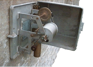 The basic parts of a wire weight gage include a drum wrapped with a single layer of cable, and a weight attached to the end of the cable. A readable disc, graduated in tenths and hundredths of a foot is attached to the side of the drum. A Veeder counter, reading in whole feet is also included. One complete turn of the drum represents one foot of vertical movement of the weight. To take a reading of stage, perform the following: