Category Archives: Equipment
HydroLynx 5096 – Transfer Data
- Locate appropriate SA1, DAT and SA2 files on laptop and transfer to network drive (e.g., Q:\StationDocs\199 – Fillmore Sanitation\Records\2015)
- Open Hydstra Explorer (HYEXPLORE) and select from the menu tree: Programs by Function > Hydstra/TS – Time Series > Hydstra Data Management > HYDMWB – Data Managers Workbench
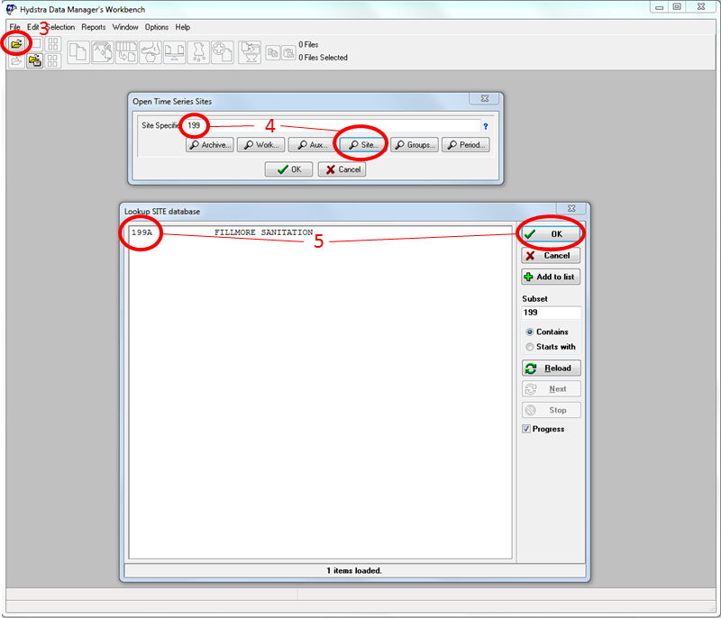
- Press the Open folder icon or select File > Open
- In the Open Time Series Site dialog box that opens, enter the site number in general format (e.g., 199) in the Site Specifier field and press the Lookup Site button
- Select the specific site (e.g., 199A) that appears in the dialog box and then press OK
- In the Open Time Series Sites dialog box confirm that the proper site is shown, then press OK
- Single-click the site icon that has an A at the end (e.g., 199A A) and select File > Copy
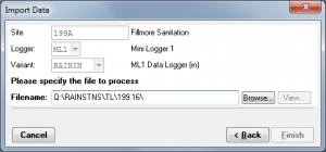
- Select File > Import Data.
- It is likely Hydstra will still “remember” importing ML1 data from previous site visits; therefore, you need to change the data type. Press Back until Logger is highlighted and select HYD from dropdown
- Press Next to highlight Variant and select RAININCH from the dropdown
- Press Next to highlight Filename and Browse to proper DAT file on network drive
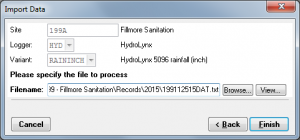
- Press Finish and a new B file is created on the Data Manger’s Workbench
- Drag the C file to the B file and release
- In the Merge Files dialog box, select the Resolve Overlaps: Split blocks if necessary, preserving C File data radio button, verify the Delete Source box is checked and press OK
- Double-click the B file to open the work file
- In the dialog box that opens, double-click the row 11.00 Rainfall (inches) – High-Resolution
- Open the block of newly imported data by selecting the block and pressing the Text tab
- Highlight all data points and press the Quality edit button

- In the Quality Edit dialog box that opens select 20 Coarser dataset used to fill gap in dataset (ie. ALERT data) from the New Quality dropdown and press OK
- Fill data gaps and continue processing data as described in Hydrological Services ML-1 – Transfer Data

HydroLynx 5096 – Download Data
Downloading ALERT data is often performed once per year. The process described below creates three files: (1) a diagnostic file prior to the data download (SA); (2) the data file (DAT); and (3) another diagnostic file after the data is downloaded (SA2). For this, you will need a laptop with RS-232 cable for communicating with the Hydrolynx 5096 unit.
Radio transmission strength is also tested at this time. For this, you will need a wattmeter and radio scanner. Also, battery voltage and solar function should be tested.
Test Radio
 Make sure either an antenna or dummy load is always attached to the transmitter to prevent damage to transmitter.
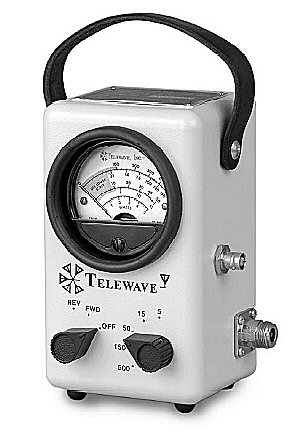
1. Use wattmeter set at the following:
• FWD and 15 watts – should read > 5 watts
• REV and 5 watts – should read < 1 watt. If reverse power is greater than a few watts (1-2), check the following:
→ Antenna at correct length for frequency (ALERT2 – 171.925 MHz) – adjusted antenna = 33.75″; omni with radials = 28″)
→ Antenna damage (bent, dented, excessive corrosion, etc.)
→ Damaged cable or fittings
2. Use scanner to confirm transmission
3. Use Novastar5 and vcwatershed.net to confirm arrival at base station
Download Data
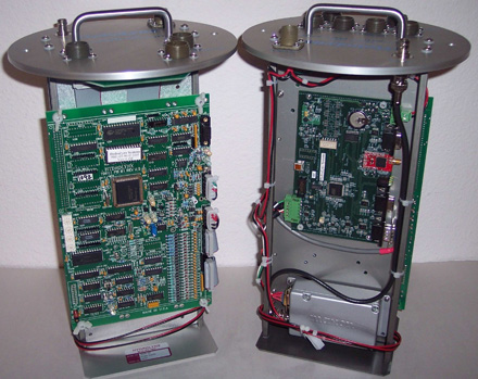
- Unscrew two black nuts from top plate
- Grasp handle, lift slightly, then rotate 90 degrees to ensure that wiring does not catch on threads before lifting fully out of the can
- Connect unit to laptop via RS-232 serial cable and with 9-pin connector
- On field laptop, open PuTTY
- Under Session, confirm that the serial line is set to COM1 and the speed is set to 9600 baud
- Further under Session, select Logging and then select the Session Logging: All session output radio button
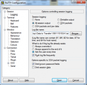
- Browse to the appropriate location (data folder on the hydrographer’s laptop), enter name in SiteMonthDayYear format, followed by the letters “SA1” (e.g., 199111515SA1), then press Save
- Press Open to activate a terminal session
- Enter command showall
- Confirm and record the following:
- Real Time
- RAW Reading
- Reset Count
- (Memory) Percent Used
- Close window
- Reopen PuTTY and repeat steps 5 and 7; however, the file name shall be followed by the letters “DAT” (e.g., 199111515DAT)
- Again press Open to activate a terminal session
- Enter command get-mem
- Press Close when finished downloading data
- Reopen PuTTY and repeat steps 5 and 7; however, the file name shall be followed by the letters “SA2” (e.g., 199111515SA2)
- Again press Open to activate a terminal session
- Enter command showall
- If necessary, change time on 5096 to match computer’s time in 24-hour format with hours and minutes separated by a comma (e.g., time= 13,15 for 1:15 PM) and press Enter
- Enter command align to synchronize all internal sensor timers
- After confirming that all files (SA, DAT and SA2) have been downloaded, enter command clear-mem
- Enter command showall to verify memory has been reset (Percent Used should read 0.00%)
- Press Close
- Tip rainfall bucket 3 or 4 times to confirm transmission via radio scanner (which should be set to same frequency as transmit signal from site)

Multimeter
- Turn on the multimeter (volt-ohm meter) and make sure it is set to test direct current, or DC (the V with the solid, not wavy line, next to it), at a range of 20 volts
- Touch the red test lead to the red positive (+) pole on the battery and the black test lead to the black negative (-) pole on the battery
- Record the voltage displayed on the multimeter
- Voltage should be greater than 12.5 volts; if not replace battery
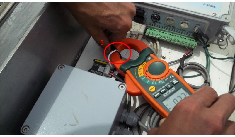
Amp Clamp Meter
- Prior to site visit, determine how many amps the solar panel can push
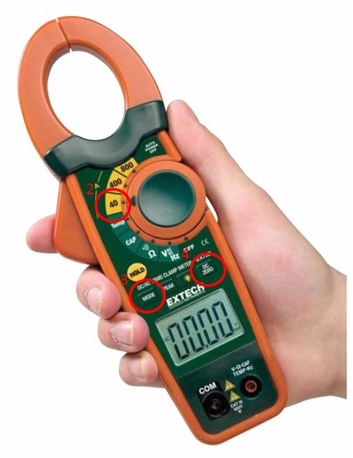
- At site, set dial to 40 amps
- Toggle button mode to DC
- Clamp around black wire (in DC circuits, black is “hot”) and center vertically
- Press DC zero button
- If taken in full sun, reading should be at or near panel capacity (Ron, are there any hard numbers we could put in here?)
- Make sure to return dial to off position
Solar and Battery
Solar Voltage
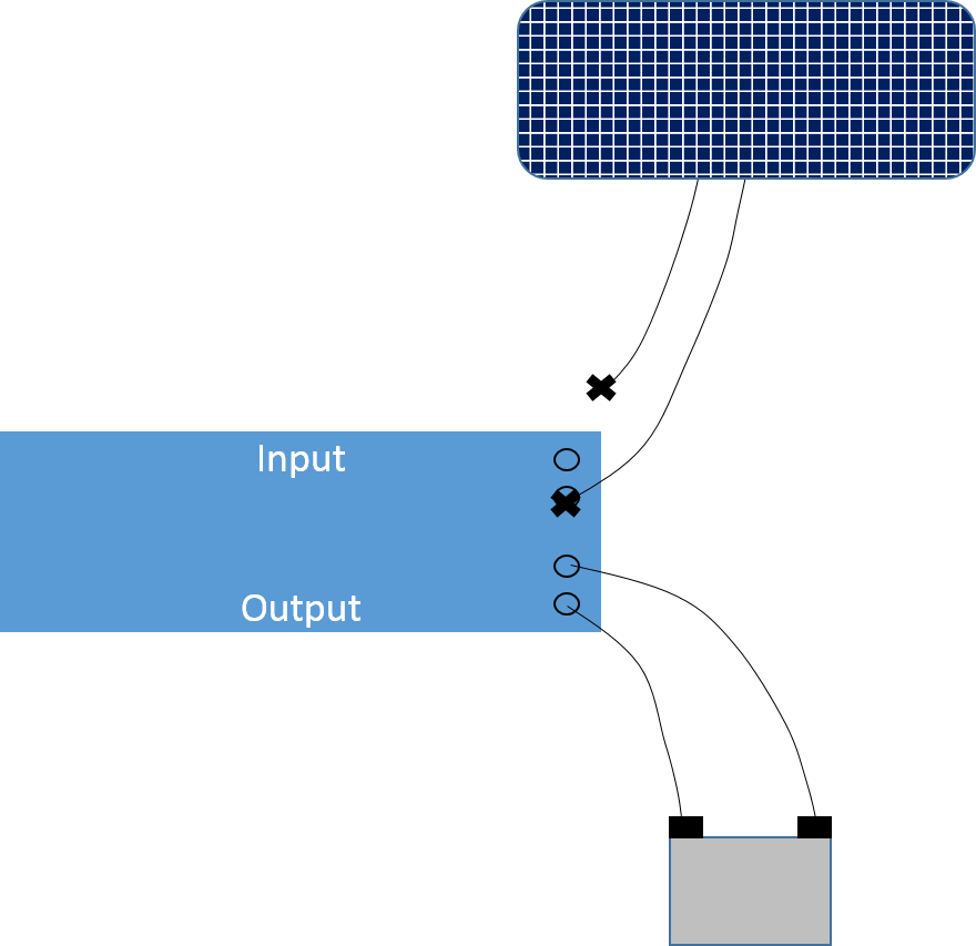
To test solar voltage (voltage coming directly from solar panel), disconnect one lead from the input terminals and place voltmeter probes on the X’s. Reading should be greater than 14 volts. If not, look for loose connections and damaged solar panel.
Reverse Voltage
To test reverse voltage (voltage passing through the regulator from the battery), disconnect one lead from the input terminals and place voltmeter probes on the X’s. Reading should be less than 0.20 volts (0.50 volts is marginal). If not, replace solar regulator.

Battery Voltage
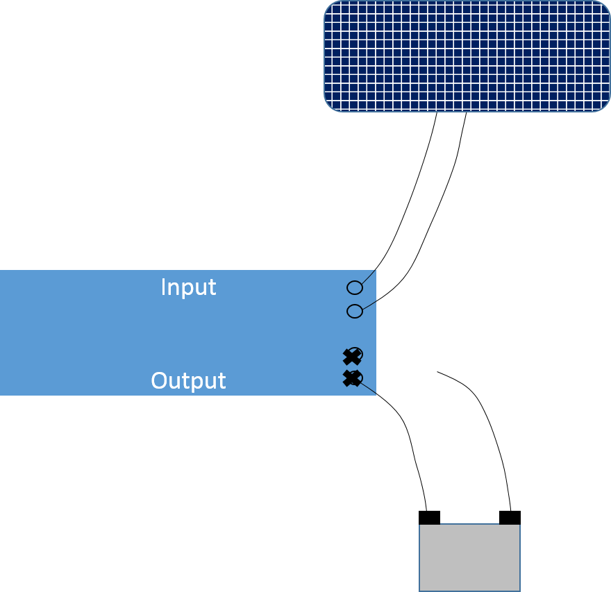
To test battery voltage, disconnect one lead from the output terminals and place voltmeter probes on the X’s. Reading should be greater than 12.5 volts. If not, replace battery.

Charging Voltage
To test charging voltage (voltage coming through regulator), disconnect one lead from the output terminals and place voltmeter probes on the X’s. If the voltage is greater than 14 volts, replace solar regulator.
Make sure all leads are reconnected to appropriate terminals when finished.
Stevens Shark – Download Data
- Turn on Bluetooth capability (procedure will vary by laptop)
- Click on appropriate site from list
- If site does not automatically connect, use the password 1610
- Open WinComLog
- Select correct COM port
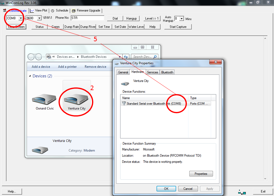
- Follow standard directions for downloading data from the ML1 here
Standard Rainfall Gauge – Maintenance
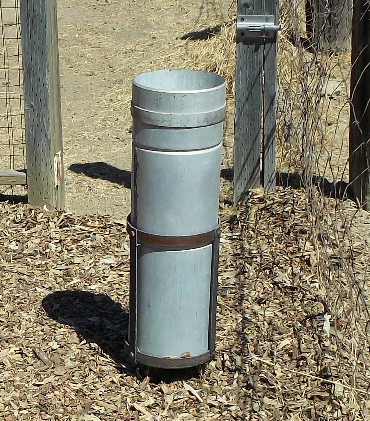
- Remove funnel from top of can and clean all dirt and debris
- Locate measuring mark on side of can; if no mark present, use the seam of the can
- Measure distance to oil surface from rim of can
- Record distance in yellow field book and subtract from previous visit to determine depth of rainfall
- If oil cap has turned white/milky:
- Pump material into “ook” container
- Add 1” of oil to can
- Measure new distance to water surface and record value in yellow field book
- Replace funnel on top of cap
Hydrological Services TB3 – Maintenance
This is the tipping rainfall bucket used at most rain gauge sites. Field maintenance is often performed concomitantly with data downloads, so please refer to this when servicing TB3 units.
Cleaning
- Loosen three screws at bottom of TB3 and remove circular enclosure
- Clean funnel and enclosure using paintbrush and/or damp rag
- Turn enclosure over an unscrew syphon
- Apply grease to syphon O-ring, if necessary
- Remove and clean filter screen
- Reassemble filter screen and syphon, hand-tighten back on to enclosure
- Remove debris and clean bucket assembly
- Verify base is level by utilizing bullseye levels
- Reattach enclosure and tighten 3 screws at bottom of TB3
Annual Maintenance
To decrease the likelihood of lost data, the 3.6V battery in ML1s must be changed each year during annual maintenance runs. Also, rain gages must be calibrated each year.
Dynamic Test
Prior to this dynamic test, disconnect TB3 from the terminal block (preferred) or from the transmitter. After the test is complete, make sure to reattach TB3 and confirm tips via website.
- Download data and clear ML1
- Place funnel back on top of TB3
- Set tripod on top of funnel
- Fill calibration cylinder until meniscus forms on top
- Screw on 100 mL nozzle taking care not to spill water
- Set on tripod, open valve and wait for water to drain out of bottle
- Target is 82 tips, but a range of 78-86 (5%) is acceptable
- Download data into calibration file and clear ML1 again
- If number of tips is out of range, perform static calibration below
Static Calibration
- Fill syringe with 10 mL of water
- Slowly add water to bucket on one side of TB3
- When bucket tips, record volume expelled from syringe
- Target is 6.8 mL, but a range of 6.46 – 7.14 mL (5%) is acceptable
- Repeat calibration on other side
- Use set screws underneath each bucket to increase or decrease the amount of water needed to tip the bucket
- Once calibrated, perform dynamic test (above) again