Category Archives: Site Type
WaterLOG H-350XL/H-500XL – Transfer Data
Stream data downloaded from equipment in the field should ideally be transferred immediately from temporary media (e.g., USB key) to a folder on the laptop, and should be stored in the SiteMonthDayYear format (e.g., 800a080615).
- Locate appropriate file on laptop and transfer to station folder on network drive (e.g., Q:\STATIONS\TL\800A\2015\Misc)
- Open Hydstra and select from the menu tree: Programs by Function > Hydstra/TS – Time Series > Hydstra Data Management > HYDMWB – Data Managers Workbench.
- Press the Open folder icon or select File > Open
- In the Open Time Series Sites dialog box that opens, enter the site number in general format (e.g., 800) and click the Lookup Site button
- Select the specific site (e.g., 800A) that appears in the dialog box and then press OK
- Press OK in the Open Time Series dialog box
- Single-click the site icon that has an A at the end (e.g., 800A A) and the select File > Copy
- In the Select Work File dialog box that opens, Select B as the New DataSource and then press OK; a new file icon is placed on the workbench (e.g., 800A B)
- Select File > Import Data and navigate to appropriate file on the network drive, as described in step 1, and then press Open
- Press Finish in the Import Data dialog box and close the event log that appears in Hydstra Explorer; a new file icon is placed on the workbench (e.g., 800A C)
- Drag the C file to the B file and release
- In the dialog box, select the Resolve Overlaps: Split blocks if necessary, preserving the C file radio button and press OK
- Double-click the B file to open the Work File dialog box (the end date of the 232.00 variable should be modified to match the date and time of the site visit)
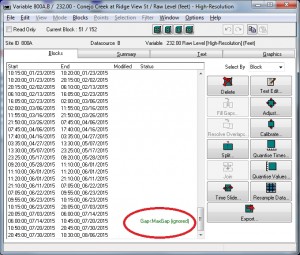
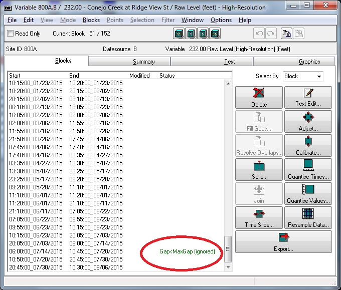
- Double-click variable 232.00, which will open the High-Resolution data set
- Most of the time, Gap<MaxGap (ignored) will be displayed between the previous data set and the data set most recently imported
- To eliminate this gap, select the block of data immediately below this status and select Split
- In the Split Block dialog box, add five minutes to Split Time (e.g., 10:50:00_07/20/2015 becomes 10:55:00_07/20/2015) and press OK; this will create an additional block of time
- Select the new block and the one immediately above it (this should be the one that has the Gap<MaxGap (ignored) status) by shift-clicking both
- Select Fill Gaps and from the dialog box that opens, select the Extend Backwards (add a new point to the start of the second block) radio button and 1 Good Unedited Data from the Inserted Quality dropdown; press OK
- A new block is created which spans the existing blocks; both the new block and the block below now display Yes in the Modified column
- Close the dialog box and press Yes to save your changes and then close the Work File dialog box
- Finally, drag the B file to the A file and select the Merge (preserve B File data if duplicates) radio button, making sure the Delete B File option is checked
- Press OK and close event log that appears in Hydstra Explorer
WaterLOG H-350XL/H-500XL – Download Data
Gage height and discharge data are periodically transferred from the unit in the form of a .NEW file. After being copied to the appropriate media, the .NEW file is deleted, thereby reducing file size for subsequent downloads. Should problems arise in downloading this file, a longer term record (.WRP file) is stored on the unit and can be accessed in a similar manner. Unlike the .NEW file, the .WRP file is only deleted at the end of each water year.
The processes described below is applicable to several types of transfer media, including USB keys or PCMCIA (Flashdisk) cards
Copy .NEW File to Media
- Open lid of H-350XL/H-500XL
- Insert PCMCIA card or USB key into appropriate slot
- Press Display On/Off key to turn on display
- Stage = x.xx is displayed; record this value on front sheet
- Press ▼ key until System Status is displayed
- Press ► key, Battery = xx.xx volts is displayed
- Press ▼ key, Min Battery = xx.x is displayed
- Press ▼ key, Max Battery = xx.x is displayed
- Press ▼ key, System Resets = x is displayed
- Press ▼ key, Resets Stats Screen? is displayed
- Press Enter to reset stats
- Press ◄ key to get back to System Status screen
- Press ▲ key until Data Options is displayed
- Press ► key, Data Memory OK is displayed
- Press ▼ key until Copy Files is displayed
- Press ► key, Copy All 2 Ext Card? is displayed
- Press ▼ key until Copy .NEW to USB or Copy .NEW to Card is displayed
- Press Enter, Copying [site].NEW is displayed
- When copying is completed, Enter to Erase .NEW is displayed
- Press Enter, Erasing .NEW is displayed
- Press Esc until Stage = x.xx is displayed
- Remove PCMCIA card or USB key
- Press Display On/Off key to turn off display
- Verify that Scanning is On is displayed
Copy .WRP File to Media
- Open lid of H-350XL/H-500XL
- Insert PCMCIA card or USB key into appropriate slot
- Press Display On/Off key to turn on display
- Wait a few seconds and the instrument should give a gage height reading
- Press
- Push ▼ key until Data Options is displayed
- Push ► key, Data Memory OK is displayed
- Push ▼ key until Copy .WRP to Card or is displayed
- Push Enter, unit should display the file that is being copied
- When the copying is complete, Done, Press Any Key is displayed
- ERASE NEW FILE
- Remove the PCMCIA card or USB key
- Push Display On/Off to turn off display
Clear Internal Memory
This process should be done on a yearly basis on the first download after the start of the new water year if the data for the previous water year is known to be complete. Be sure to download .NEW and .WRP files before completing this process.
- Open lid of H-350XL/H-500XL
- Insert PCMCIA card or USB key into appropriate slot
- Press Display On/Off key to turn on display
- Wait a few seconds and the instrument should give a gage height reading
- The scanning must be turned off in order to clear the memory not the logging
- Press the Esc key until back to Data Options
- Arrow Down to Scan Setup
- Right Arrow, Scanning [ON] should now be displayed
- Press Enter and ON should now be flashing
- Press ▲ key to turn the scanning off, then press Enter
- Press the Esc key until back to Scan Setup
- Press ▲ key until Data Options is diplayed
- Press ► key, Data Memory OK should now be displayed
- Press ▼ key until Erase Internal Data is displayed, then press Enter
- When asked Are You Sure?, press Enter
- Press the Esc key until back to Data Options
- Press ▼ key until Scan Setup is displayed
- Press ► key, Scanning [OFF] should now be displayed
- Press Enter and OFF should now be flashing
- Press ▼ key to turn the scanning on, then press Enter
- Press the Esc key until back to Scan Setup
- Press ▲ key to Sensor Input Setup
- Press ► key, Stage Setup should now be displayed
- Push Display On/Off to turn off display
Sommer RQ-30 – Transfer Data
Sommer RQ-30 – Download Data
SonTek HydroBoard – Transfer Data
SonTek HydroBoard – Operate Equipment
In this package, an Acoustic Doppler Profiler is mounted on a floatable platform, which resembles a Boogie Board. Position is tracked using a GPS on the boat that communicates with a land-based station and is, therefore, capable of centimeter-accurate results. At least four transects are required for an accurate measurement.
GPS
- Set up tripod in alignment with cross section
- Install charged batteries and mount Real Time Kinematic (RTK) GPS on top of tripod
- Set up GPS in view of cross-section to be measured and make sure you have clear view of the sky
- Mount antenna on side of GPS
Floatable Platform
- Mount tracker on boat
- Mount Acoustic Doppler Profiler (ADP) on boat; be sure to set ADP to yellow line
- Mount Power Communication Module (PCM) and connect cables from antenna and ADP to PCM
Laptop
The initial setup of the HydroBoard is done using a laptop connected to the ADP via Bluetooth connection.
- Plug in dongle (external Bluetooth adapter) to laptop
- Plug in power cord from dongle to laptop
- Press On/Off switch to turn on dongle
- Open RiverSurveyor Live
- Turn on power switches on ADP and PCM (GPS has two lights – power and GPS; (PCM has four lights – power, radio, RTK and GPS)
- Connect to River Surveyor on laptop
- Make sure Parani Bluetooth Connection is checked
- Press Connect
- Select S5 Unit
- Press Connect
- Bring up startup screen (goal: make all red lines turn green)
- Go to bottom of screen and perform System Test
- Dialog box opens; press Start
- Dialog box opens to verify system pass; press Close
- Press Change Site Information and input appropriate information (note: boat is R boat) – not all fields are required
- Press Compass Calibration; dialog box opens; press Start
- During calibration, a second person should pick up the boat and wiggle it back and forth
- Dialog box will indicate Pass if the calibration is successful (calibration score should be close to 10, a score of 9 is acceptable)
- Close window
- Press System Settings and set the following fields to these values
- Transducer Depth – 0.24 (note: will change due to new board)
- Screening Distance – 0
- Salinity – (variable – use salinity meter to determine correct value)
- Magnetic Declination – 12.5
- Track Reference – bottom track
- Depth Reference – vertical beam
- Coordinate System – ENU
- Smart Pulse – enabled
- Press Enter
Blackberry
Once the initial setup is completed, a handheld PDA is used to enter data and track progress of the ADP.
- Disconnect laptop Bluetooth connection and connect Blackberry Bluetooth (password: 1610)
- Press soft key Start to get to Programs
- Select River Surveyor Live
- Search for unit
- Press Connect when found
- Press Start System
- Press Start Edge
- Fill in parameters and press OK
- Deploy fins on HydroBoard and place unit in water
- Press Start Edge and wait until you get at least 10 samples at the edge
- Set bank and distance from center of HydroBoard to edge of water; press OK
- Pull HydroBoard across creek at a consistent speed and no faster than water velocity
- Once across the cross-section and after 10 samples at edge, enter distance and press End Edge
- Press End Transect
- For next measurement, press Continue
- Repeat steps 6-10 a minimum of four times
SonTek FlowTracker – Transfer Data
- Connect unit to computer using 5-pin cable and serial connection (with or without USB adapter)
- Press yellow power button to turn unit on
- Open SonTek FlowTracker program
- Press Connect to a FlowTracker
- On Connect to serial port dialog box, select proper COM port and confirm Baud rate: 9600
- Press Connect
- Press Recorder; dialog box opens
- Select files for download (e.g., 800A0806.15)
- Press Browse to navigate to destination folder (e.g., Q:\STATIONS\TL\800a\2015\Misc)
- Press Download
- Confirm .WAD files transferred to proper location
- To erase .WAD files, select all appropriate (e.g., 800A0806.15) and press Format
- When completed, press yellow power button to turn unit off and disconnect unit from computer
- In Windows Explorer, navigate to folder (e.g., Q:\STATIONS\TL\800a\2015\Misc), select file (e.g., 800A0806.15.WAD) and rename using SiteMonthDayYear format (e.g., 800a080615.WAD)
- In FlowTracker, press Open a FlowTracker file, navigate to newly named .WAD file and press Open
- Press Printer button, print first page and attach to front sheet from site visit
SonTek FlowTracker – Operate Equipment
- Press yellow power button to turn unit on
- Press Enter to get to main menu
- To begin a measurement, press 3 (Start Data Run)
- Press 1 (Name), input name using SiteMonthDay format (e.g., 800A0806) and press Enter **this represents a change from the normal naming convention because the FlowTracker only allows 8 characters for the site name – this will be corrected later during the data transfer phase**
- Press 2 (Extension), input the two-digit year (e.g., 15) and press Enter
- Press 9 (Accept name)
- On next screen, press 1 (Site), input name using SiteMonthDayYear format (e.g., 800A080615) and press Enter
- Press 2 (Operator), input initials of hydrographer (e.g., TL) and press Enter
- Press 9 (Start)
- On next screen, press Enter
- Place meter in water away from obstacles and press 1 (Run Test) to perform the Automatic QC Test
- If starting transect at Right Edge of Water, press 4 (REW/LEW) to toggle to REW
- Press Set Location, input tagline distance at edge of water (usually right side) and press Enter
- Press Set Depth, input depth reading (usually 0) and press Enter
- Move to first vertical, input tagline distance and depth using steps 13 and 14
- Set meter to 0.6 depth of vertical and press Measure
- Review error messages and press Enter to move to next
- When error messages are complete, Press 1 (Accept) to move to next vertical
- Repeat steps 15 – 18 for each vertical along remainder of cross-section
- When finishing edge of water is reached, press 1 (End Section) twice
- Review error messages and press Enter to move to next; press 1 (Accept) to move to QC screen
- Press Enter to move to discharge calculation screen
- Presss – (Calculate Discharge) twice
- To save measurement, press 0
- Press yellow power button to turn unit off
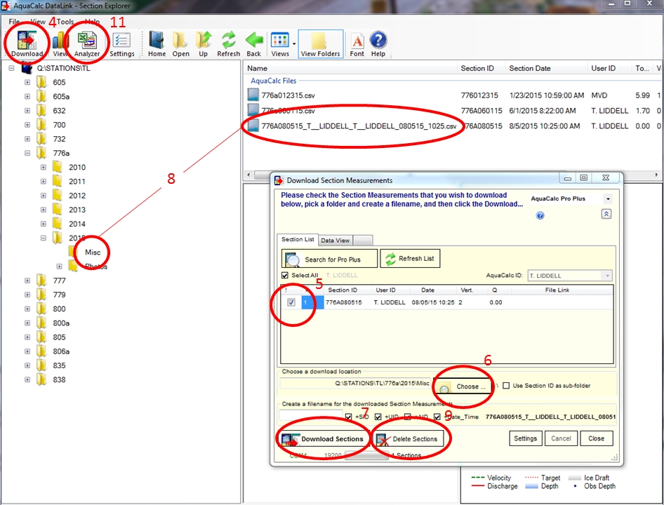
JBS AquaCalc Pro+ – Transfer Data
- Connect AquaCalc Pro+ to compter via USB cable and press On/Off
- Press 3 (Connections) and verify that Connection is set to USB
- Open AquaCalc DataLink3
- Press Download
- In Download Section Measurements dialogue box, select measurement to be downloaded (e.g., 776A080515)
- Under Choose a download location, press Choose and navigate to appropriate folder location (e.g., Q:\STATIONS\TL\776a\2015\Misc)
- Press Download Sections
- Verify transfer of .CSV file to appropriate file location (e.g., 776A080515_T__LIDDELL_T__LIDDELL_080515_0709.csv)
- To remove discharge measurement from Aquacalc Pro+, re-select section and press Delete Sections
- To rename tranferred file so that it follows the SiteMonthDayYear naming convention (e.g., 776a080515), right-click CSV file and select Rename
- Press Analyzer; MS Excel document opens
- Select Import and Edit Here tab, press Import AquaCalc Pro Output File, navigate to the newly transferred file and press Open
- Select Summary for Printing (5×8) tab, print first page and attach to front sheet from site visit